Categories
CAM-POST provides a series of extractor interfaces seamlessly integrated within the following popular CAM systems: CATIA, NX-CAM, Creo-NC, Mastercam and TopSolid. These interfaces are used to “extract” the necessary data from the CAM system prior to launching the simulation process (either GENER for running a graphic post-processor, or CErun for G-code simulation).
The new extractors available with CAM-POST V21 offer a consistent “look-and-feel” regardless of the CAM system being used. Additionally, V21 extractors also support Multiple Setup jobs. These jobs can handle multiple operations in which the machined part is either transferred from one fixture to another on the same machine, or moved on to another machine. In either case, the stock in process inherits the results of previous operations. The unified extractors provide settings for handling everything related to mounting references, part transfer, rotation or flipping and fixture compensation calculations.
The command LOAD/ SETUP at the beginning of each operation allows the selection of different steps of the program.
The screenshot below illustrates the new extractor in the context of a Multiple Setup program using three different mounting references.
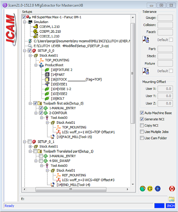
The extractor includes the information defined in the machining process structured as follows.
Setup Tree / Program Tree / Tool Path Tree
- The Setup Tree may contain multiple Program Trees
- In case the “Use Multiple Jobs” option is unchecked, each Setup Tree will contain one job
- If the “Use Multiple Jobs” option is checked, each Program Tree will contain one job
- Setups, Programs and Tool Paths can be included / excluded by checking or unchecking the leading check-box
- A Setup can be attached to the previous setup
- Attached setups can be removed
Product Tree / Geometry Type / Multiple Stock-Axes
- Product Trees are included in each Program Tree
- The Product Tree is a sub-node of the Stock Axis for multiple stock axes
- This structure indicates that all selected geometry nodes will be mapped from the mounting reference to the mounting stock axis.
- The offset of the mounting reference can be manually adjusted
- The same mounting reference can be used in different programs and the stock axis can have different user offsets
- The “Mounting offset” control is active if the mounting reference node is selected
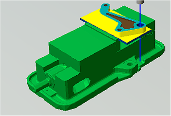
The example below illustrates the three consecutive steps of the Multi Setup machining process extracted.
First setup, surfacing and drilling, program origin= TOP, position TAG=Top
LOAD/SETUP, 1
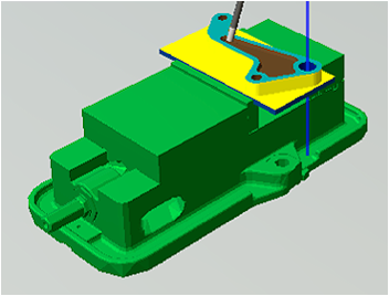
Second setup, 5-axes swarf cutting of the in-process stock transferred to another mounting reference, program origin=Ref, position TAG=Ref
LOAD/SETUP, 2
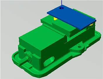
Third setup, surfacing and 5-axes swarf cutting of the flipped in-process stock, program origin=Ref, position TAG=Bottom
LOAD/SETUP, 3
Benefit to User.
Facilitate the programmer’s work in the context of multi setup machining process and virtual machine simulation.
For more information or comments, please do not hesitate to contact us at TechTipTuesday@icam.com