Categories
While some 5-axes milling centers may have an unlimited rotary axis (usually a table), most others have hard travel limits on both rotaries, whether tables or heads. In some cases, these travel limits are due to the mechanical construction of the rotating device. In other cases, though, rotaries simply have restricted travel boundaries due to electrical cables and/or coolant lines running inside.
Each time one of these rotaries reaches a travel limit during machining, the post-processor has to retract the tool, reposition to an alternate kinematic solution within travel limits, then return to the last position on the part. This action is called a rotary turn-around (RTA).
Post-processors can be set to automatically force an RTA whenever rotary over-travel is detected.
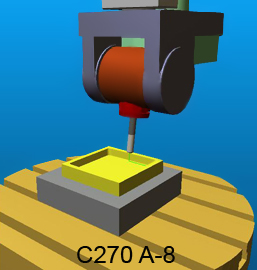
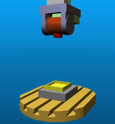
In the example illustrated here, the machine has a C-axis table and an A-axis head. The table can travel from -270° to 270°.
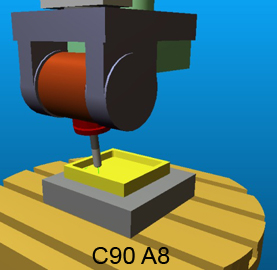
In the left illustration, the C-axis has reached its upper travel limit during a contouring operation. The post-processor initiates an RTA to the alternate position illustrated on the right, where machining is resumed.
To activate the “Rotary Turn-Around” feature in CAM-POST, the following command must be inserted in the Cutter Location data (i.e., aptsource file):
LINTOL / ROTREF, ON
Optionally, further arguments can be used on another command to specify the amount to retract along the tool axis at the current feed rate, as well as an additional amount to retract in rapid, also along the tool axis:
LINTOL / ROTREF, BACK, feed_distance, RTRCTO, rapid_distance
While the RTA post-processor feature has considerable benefits, as it prevents rotary over-travel errors, the fact that machining is temporarily discontinued during repositioning may raise concern on finishing operations where the tool can leave a visible mark on the part.
A better solution would be to prevent the over-travel (and the ensuing RTA) ahead of time, specifically on the initial positioning move at the start of the tool-path.
In the example above, the contouring operation started at a table position of C-90 and stopped due to over-travel at C270. After the RTA repositioned the table at C90, machining continued from C90 to C135. If the operation would have started at C-270 instead of C-90, the table could have moved without interruption from C-270 to C135.
This is precisely what CAM-POST would do when its “Winding Control” feature is activated. To activate this feature, the following command must be inserted in the Cutter Location data:
LINTOL / WIND, ON
With this command active, the post will rotate a rotary axis as much as necessary or possible on the positioning motion, so as to avoid an over-travel condition on that rotary during the cutting process.
Winding control should be activated on any post-processor having rotary axes with limited travel in excess of 360 degrees.
Benefit to User
The rotary winding feature uses path-planning look-ahead to automatically preposition rotary axes so as to minimize or eliminate RTA resulting from rotary over-travel.
For more information or comments, please do not hesitate to contact Phil at TechTipTuesday@icam.com