Categories
Using tool length to improve linearization
“Linearization” is a function of post-processing, for machines with rotary axes, which subdivides a motion into smaller steps to ensure that the tool tip follows the path intended (i.e., a straight line). Many modern controllers have an RTCP function that does this automatically (e.g., Siemens TRAORI, Fanuc G43.5, Heidenhain M128…). When this function is enabled on the controller, XYZ positions are expressed in part coordinates and only the end-point of each 5 axis move is necessary.
Why linearize?
When the XYZ coordinates of a motion drive the physical axes of the machine, instead of the tool tip position as expressed in part coordinates, then the post-processor must adjust the physical linear axes to account for the distances between rotary head center and tool tip, and between rotary table center and part origin.
In the image below, the CAM system has output a single motion with a rotary component between points #1 and #2. The straight green line at the tool tip is the intended motion. The curved green line at the tool top is the motion of the physical machine axes. The post-processor (or RTCP controller function) must subdivide the motion into smaller steps to drive the physical axes along the upper curve so as to produce the straight line motion at the tool tip, as signified by the multiple tool images.

If linearization is not enabled, either in the post or controller, then the motion of the physical axes would be the straight red line at the tool top, and the tool tip would instead follow the curved red line at the bottom, resulting in a gouged part, or worse.
How many steps?
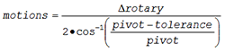
In the post-processor, linearization is primarily controlled by specifying the maximum distance the tip of the tool can deviate from the intended straight line motion. The finer (i.e., smaller) the tolerance, the more motions that are required to keep the tool tip within the tolerance. The greater the “pivot” distance between the rotary axes center and the tool tip or part origin, the more motions that are required to stay within tolerance. The relationship between these can be expressed as follows:
How can tool length improve linearization?
As seen above, a longer pivot requires finer subdivision (i.e., more motions) to stay within tolerance. On machines with one or more rotary head axes, adding the expected tool length to the rotary pivot distance will produce more accurate results and less possibility of gouging.
The expected tool length can be specified using the following command:
![]()
- The length is the expected length of the tool. Most CAM systems have some means of passing the tool length to the post-processor. If not, you can use a fixed value, set to the maximum possible tool length usable on the machine.
- OFF omits the tool length from linearization calculations.
- ON re-enables this feature, using the last specified length.
Benefit to User
Including the expected tool length into post-processor linearization calculations will produce more accurate results and less possibility of gouging.
For more information or comments, please do not hesitate to contact Phil at TechTipTuesday@icam.com